- Textile Accessories
- Shuttle Loom Parts
- Textile Equipment
- 1511 Textile Machine Parts
- 1515 Textile Machine Parts
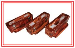
- GA615 Shuttle Loom Parts
- Textile Hardware And Tools
- Weaving Machinery
- Textile Auxiliary Equipment
- Textile Picker and Buffer
- Textile Wooden Parts

Huixian Xinda Textile Machinery Accessories Co., Ltd. has long provided 44" loom accessories C3 tension sector rod, which is connected with the C29 rear beam (rear rocker) of the loom. The total length of C3 tension sector rod is 58 cm, the width is 113 mm, the thickness is 98 mm, the inner diameter of the rear beam hole at the tail is 28 mm, the diameter of the middle C26 hole is 18 mm, and the inner hole diameter of the front C8 is 20 mm, Tension sector bar C3 is divided into left hand and right hand. It is made of pig iron (HT15-33). The weight of a single sector bar is 2.4kg.

The sector rod of textile fitting C3 is sleeved on the rear rod C29, hook the brake rod spring C38, install a set of brake rod C9, rotate the bending shaft to make the brake rod rotor C16 contact with the bending shaft cam D11, correct the left and right levelness and surface tightness, and file the brake rod support foot to adjust if it is not aligned.

Correction method of tension adjusting device: bend the shaft at the upper center, adjust the supporting head screw on the brake rod supporting foot to make the spacing between rotor C16 and cam D11 3 mm, and check the spring force. The rotor C16 should rotate flexibly, so that the oil hole of rotor core C31 should be upward and outward, and the inner side of the core should be flush with sector brake rod C9.

Connect the connecting rod C4 with the sector tension rod C3, make the adjusting weight C5 vertical, and correct the distance between the lower part of the weight and the lower end of the adjusting weight rod to be 25mm; After correction, the distance between the inner side of post C29 and the rear edge of wallboard P1 is 32mm; The distance between the front end of the tension hammer rod C14 and the upper edge of the wallboard is 108 mm, the bending shaft is in the upper center, the tension rod is placed flush with the upper part of the brake, the rear beam C28 and the stable motion rod C13 are put on, the distance between the rear beam and the rear rod C29 is 46 mm with the rear setting gauge, and the supporting screws of the stable motion rod are tightened.

Use the warp position line setting gauge and take the breast beam P3 as the benchmark to correct the consistency of the two sides of the reed Q1, the middle winch o38 and the rear beam C28. The high side of the rear beam shall prevail, and the low cushion shall be corrected; If the middle twisted bar is less than 3mm lower than the setting gauge, it can be corrected by padding on both sides. If the height difference is large, the upper and lower positions of suspension feet o101, o102 or O15 of the amenorrhea frame can be adjusted. The position of the adjusting rod stop ring C40 in the guide frame C15 shall be determined according to the weaving variety.


